Variable lift to get onto optimum glid path reduces peak acceleration.
Our reentry simulations indicate we can keep the SSTT under 900 degrees C all the time. This is because the rocket is suborbital, small, and lightweight. Compared to shuttle reentry we will have much lower temperatures (about 900 C compared to 1650 C) and for much shorter time (about 2 min compared to 20 min).
Reentry from a tether generates less heat, for shorter periods than reentry from orbital speed. This makes design for reentry much easier for an SSTT than from full orbit.
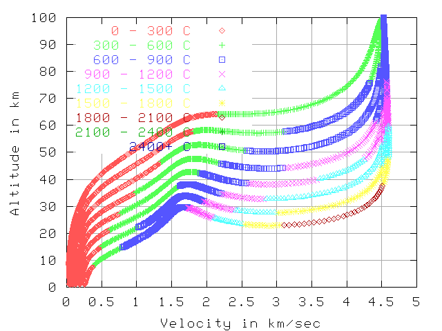
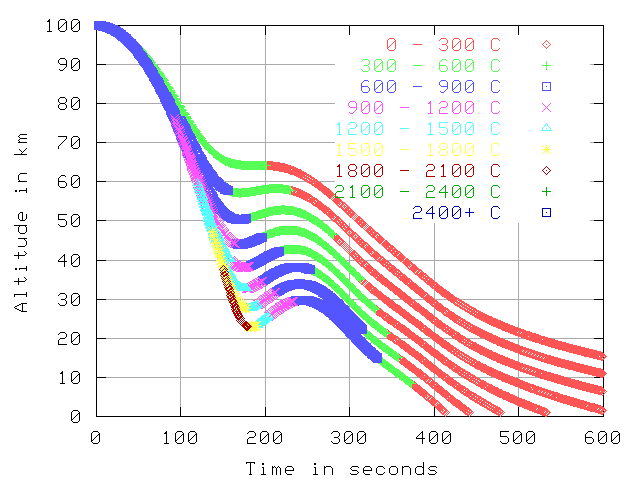
The following graphs are designed to illustrate the differences between reentry from a tether and reentry from orbital speed. The data comes from simulation examples 51 and 52 in the SpaceTethers.com simulator. There are 4 views of the 2 data-sets, for a total of 8 graphs.
The graphs each have 8 curves for 8 blunt reentry vehicles. The y-axes shows the altitude. In the first 6 graphs the x-axes show the speed relative to the air, in the last 2 graphs the x-axes shows the time. The vehicles all have the same weight (10,000 Kg) and the same L/D of 0.5. The difference between the vehicles is in the amount of drag area they have. Thedrag areas shown are 640, 320, 160, 80, 40, 20, 10, and 5 sq-meters. In each graph the 640 sq-meter area vehicle is the top curve, as it slows down at a higher altitude. The other vehicles are in descending order according to drag area below the 640 sq-meter vehicle.
There are good heat-shield materials and methods, but designing a reliable reusable reentry vehicle is a hard problem. The idea of transpiration cooling looks good.
The larger area reentry vehicles in the graphs could only be done with some rather novel method. Something like a big parachute with an inflated rim so it would work at high altitudes. But this would not be the blunt shape that these graphs assume, so the edges of the parachute would be hotter than shown here. Still, there are some high temperature cloths so maybe this is possible.
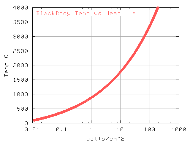
Relation of heat imput to equilibrium temp
Temp, 7.7 km/sec in inertial frame, 200 km starting altitude
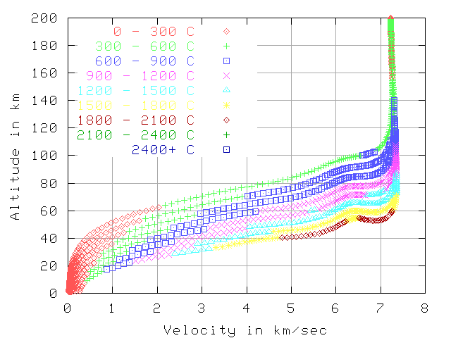 In the first 2 graphs (7.7 km/sec and 5.0 km/sec) the color indicates
the temperature at that point in reentry.
The reported temperature is simulated from stagnation point heating of a black body.
There is a nice collection of
books on reentry available online. The book we find most useful
is Hypersonic Aerothermodynamics by Bertin.
In the first 2 graphs (7.7 km/sec and 5.0 km/sec) the color indicates
the temperature at that point in reentry.
The reported temperature is simulated from stagnation point heating of a black body.
There is a nice collection of
books on reentry available online. The book we find most useful
is Hypersonic Aerothermodynamics by Bertin.
Temp, 5.0 km/sec in inertial frame, 100 km starting altitude
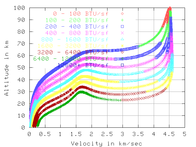
Total BTU per sq-foot, 7.7 km/sec , 200 km altitude
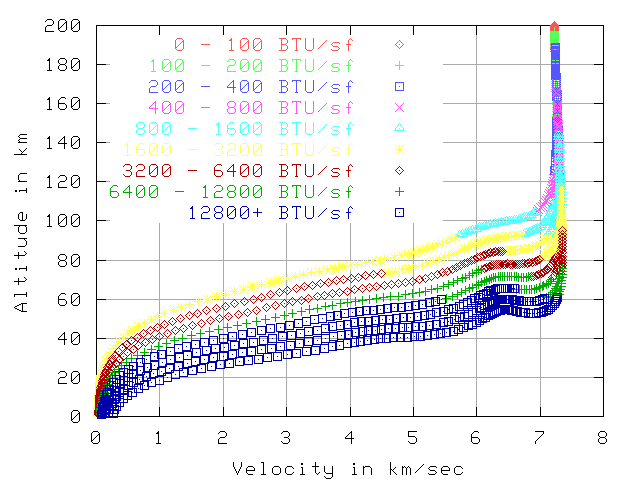 The next 2 graphs show the total BTU per sq-foot by that point in reentry.
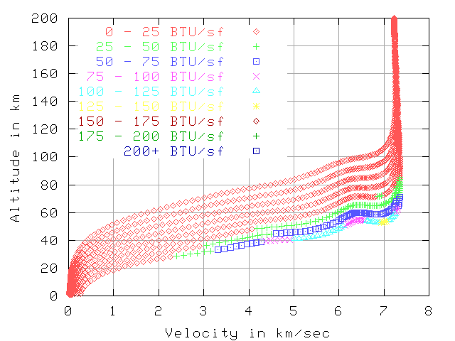
The total heat load starting from 5 km/sec is far less than from 7.7 km/sec.
This is mostly because the reentry from 5 km/sec is over much quicker.
The total reentry is about 600 seconds vs 2500 seconds, but the hot part
is about 100 seconds vs 1000 seconds.
If the vehicle is
using ablation or a heat-sink then this makes a big difference.
The 80 sq-meter vehicle has has 11402 total BTU/sq-foot when starting at 7.7 km/sec
and 1175 BTU/sq-foot when starting at 5 km/sec. This is 9.7 times the total heat.
This implies about 9.7 times the thickness of ablative material will vaporize.
The next 2 graphs show the total BTU per sq-foot by that point in reentry.
The total heat load starting from 5 km/sec is far less than from 7.7 km/sec.
This is mostly because the reentry from 5 km/sec is over much quicker.
The total reentry is about 600 seconds vs 2500 seconds, but the hot part
is about 100 seconds vs 1000 seconds.
If the vehicle is
using ablation or a heat-sink then this makes a big difference.
The 80 sq-meter vehicle has has 11402 total BTU/sq-foot when starting at 7.7 km/sec
and 1175 BTU/sq-foot when starting at 5 km/sec. This is 9.7 times the total heat.
This implies about 9.7 times the thickness of ablative material will vaporize.
Total BTU per sq-foot, 5.0 km/sec , 100 km altitude
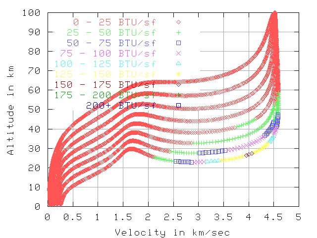
BTU per sq-foot/sec, 7.7 km/sec , 200 km altitude
 The next 2 graphs show the BTU load per sq-foot per second.
BTU per sq-foot/sec, 5.0 km/sec , 100 km altitude
Temp over time, 7.7 km/sec in inertial frame, 200 km starting altitude
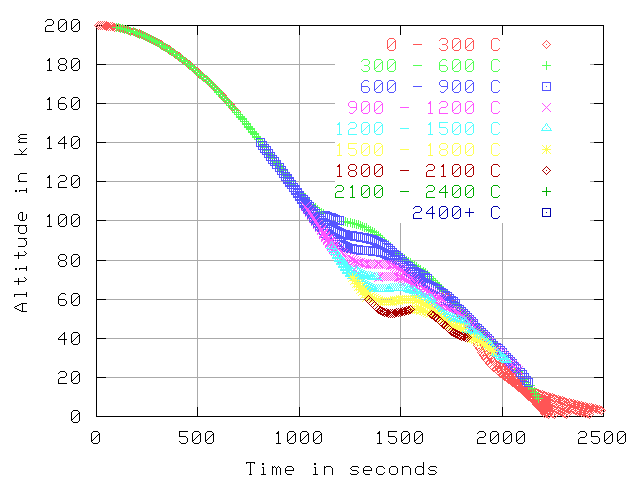 The last 2 graphs
show altitude over time with color showing temperature.
The last 2 graphs
show altitude over time with color showing temperature.
Temp over time, 5.0 km/sec in inertial frame, 100 km starting altitude
Links
- NACA 1381 A Study Of The Motion and Aerodynamic Heating of Ballistic Missiles Entering The Earth's Atmosphere At High Supersonic Speeds, 1958